| POST & AUTHOR & Vision | RSS - Ring Skeleton Structure | LTH - Launcher Transport Head | EFO - Experimental Flying Object | RSC - Rotational Slingshot Catapult |
|
Even catching or deflecting asteroids and comets for planetary asteroide defence seems possible when a huge space tug is used. For launch and construction of an oversized thruster ring take a look at RSS - Ring Skeleton Structure and LTH - Launcher Transport Head . Those tugs could get operated through a community of all spacefaring nations which are most interested to substain a clean earth orbit.

The catcher net 2.7 is attached to the Thruster Ring through belts which also carry the solarcell arrays. The Outer Ring pipes, the belts, tethers or thread are preferably made of strong and lightweight nanotube like materials.
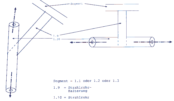
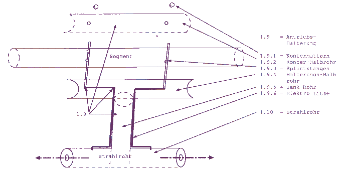
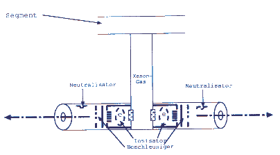
The thrusters are located in plugable complete thruster-tank units, each holding two thrusters in a thruster pipe. Each of the two thrusters fires to the opposite to itīs partner in the pipe. In conjunction with two partner complete units design were always two units are mounted conversely at the ring this allows to stop, accelerate, deaccelerate, turn the craft in each direction wanted without needing moveable thruster mountings - just through firing different thrusters. So this spacecraft is highly steerable.
Because of the complete thruster unit concept with easily changeable thrusters through plugging/unplugging the craft could get fueled and updated with better thrusters in a wash and at the same time.
In the drawing above we can see four thruster units 1.5 for turning the craft araund the disks centrum or for accelerating / deaccelerating the disk plane forward / backward or sidewards. Since this is possible just with two double units we have double redundancy.
The main propulsion thrust should come from the thrusters 1.6, which can push the the catching net towards the objects or deaccelerate to dump the. There are 12 double thruster units thought to be used at least for units together. So we have at least 3 times redundancy here.
Wouldnīt the craft get to much mass with such a lot of thruster units? If using for instance Russian SPT 60 hall thrusters each weighting about 1.2 kg for those 16 double thruster units we get about 40 kg for the thruster units without fuel.
If we would use a 100-m diameter outer ring made of CNT, this would account for about 60,000 cubic cm = 78 kg earth weight. (diameter of the pipes 6 cm, 1 mm strength of the pipe walls, diameter of the ring 100 m = 100 m x 3,1428... x 6 cm x 3,1428 x 1 mm = about 60,000 cubic cm that is about 78 kg).
I admit I used the very optimistic numbers for carbon nano tube structures (not carbon reinforced plastics) which have been used through Edwards/Westling for the Space Elevator which may not be realistic for the near future.
Using this design for asteroid deflection even for bigger asteroids would be also possible. First we would have a huge ring with a lot more of thrusters. Since we are not restricted to electric thrusters, we could add stronger chemical thrusters to the ring and use the electric propulsion mainly to transport the space tug to the asteroid. The stronger chemical thrusters would get fired, when the contact to the asteroide is made.
Since the thruster ring is also able to carry a solar sail we could place such deflection tugs far away around earth location waiting for asteroids to come. With an additional observation fleet of small solar sail satellites brought out with a carrier solar sail we could be able to prevent asteroids or comets to surprise us and taking countermeasures at the right time.
This is how I imagine steering the tug. If you take a look on top of the thrusters 1.5 are cameras 1.2.2. They shall provide a stereo look as the craft would be the turning head. When the robonaut moves his head (or his whole body when he is using a wearable monitor) to the right, the craft would turn right, when he moves the head or his body to the left, the craft would turn left. He could also move his head up and down and the craft would move accordingly. He could than steer how much the thrusters are firing for acceleration or deceleration with his hands. Also with his hands he could switch an automatic stop function were the crafts thrusters are directed to stop an acceleration or a turn he just initiated to a standstill.


| POST & AUTHOR & Vision | RSS - Ring Skeleton Structure | LTH - Launcher Transport Head | EFO - Experimental Flying Object | RSC - Rotational Slingshot Catapult |
|