| POST & AUTHOR & Vision | RSS - Ring Skeleton Structure | LTH - Launcher Transport Head | EFO - Experimental Flying Object | RSC - Rotational Slingshot Catapult |
|
As the sail has a central docking station it is also possible, to enhance the mass shift through moving the payload or daughter units of the mothership with the help of moveable docking brackets. As well displacing the center of mass up towards Sun through placing the payload accordingly if the craft carries a magazine docking station is an option. With that constellation the solar sail would "drag" itīs center of mass behind it which would produce some kind of stabilization.
Further possibilities for fuelless attitude control are moveable control bars or vanes fixed to the outside of the outer ring.
This versatility shows the usefullness of a solar sail design with a stiff outer ring gossamer structure and central payload and docking station which has ample space and possibilities for spacecraft steering as well as for convenient payload mounting and docking.
The solar sails structure constists of a stiff outer ring skeleton (1) which carries low-thrust-thruster-units (1.5 and 1.6) and solar panel rolls (1.11) directly fixed to itīs pipe body.
The area inside of the outer ring is made up mainly of the sail panels. Besides the fuelless steering options it can also use itīs thruster units for steering but also as a secondary propulsion option.
In this drawing the ballast steering panels BA and BD are rolled up to half of their unfurled area onto the sail panel rolls 1.11. That means the mass of the sail panels is shifted to the rolls of panels BA and BD and with it the sails center of mass - cm - as shown in the sails middle part is shifted into the same direction.
The center of solar radiation pressure force ( here shown as cf ) however is shifted into the opposite direction. As BA and BD are both rolled up halfway, in this case the sail is turned upwards via direction VR shown on the sail panel F while the pressure of the stronger radiation force (the opposite, fully unfurled panels have more sail area) pushes the sail down at the sail panel E. The longer the way between cm and cr the more steering inertia accrues per time unit.
By varying the length of the unrolled ballast panel segments it is even possible to shift the turning direction between the two segments which are actually used for steering according to their working ballast area.

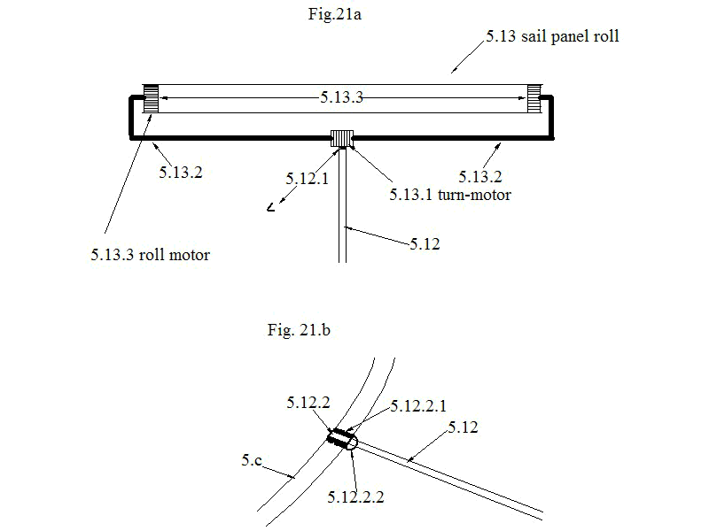
Underneath Fig. 21a describes the design of a sail panel roll 5.13 on itīs bracket. The end of the bracket telescope segment 5.12 holds a turn motor 5.12.1 which can twist the steering sail foils into a propeller like shape and enables turning the sail around itīs pole.
The two roll motors 5.13.3 are the furling motors which work together with winches on the inner ring construction of the sail craft.
Fig.21b pictures the origin of a bracket telescope segment at the inner ring construction.

| POST & AUTHOR & Vision | RSS - Ring Skeleton Structure | LTH - Launcher Transport Head | EFO - Experimental Flying Object | RSC - Rotational Slingshot Catapult |
|