Solar sail launch system
- Đ Frank Ellinghaus -
Fig.1 -
Fig.2a-2b -
Fig.2c -
Fig.2d -
Fig.3a-3b -
Fig.4a-4c -
Fig.5 -
Fig.6 -
Fig.7 -
Inner Ring -
Flying Ring -
Fig.8 -
Fig.8a -
Fig.8b -
Fig.9 -
Fig.9a -
Fig.10 -
Fig.11 -
Fig.10 -
Fig.11 -
Fig.13 -
Fig.14-15 -
Fig.16 Mobile Thruster Unit -
Fig.17 -
Fig.18 Fuelless Steering -
Fig.19-21d Solar Sail Launch System
Solar Sail Launch and self enlargement System (SSLS).
Purpose of the system is, to launch an operation ready solar sail which carries a central payload and docking station as well as ample solar cell arrays - for year long space usage directly without further space construction tasks to itīs destination point/orbit. Those solar sails may serve as communication or observation satellites supplying enough energy to provide a high bandwidth for communication. They could serve also as mothership, carrying redockable lander and prospector daughter units for asteroid exploration, mining and material extraction missions.
The system consists of the system launcher and a system sail.
The launcher
is preferably a large one like the Ariane V launcher.
In this case the launcher does not only launch the sail. It is part of the sails enlargement process and helps to spread out and enlarge the sails sail panel brackets 5.12 shown on Figīs 19, 20 and 21.Outspreading of the sail foil brackets of the solar sail is done by opening up the launcher payload compartment in segments, each pulling one sail foil roll on their bracket sidewards. Enlargement of the solar sail happens through rotating the sail with a stationary rotation platform on the launcher.
The solar sail
uses the full area of the launcher payload compartment bottom to spread itīs stiff core frame of lightweight pipe rings which carry a good part of the spacecrafts equipment, such as solar cell arrays, thruster units with fuel, electronics, instruments and a central docking station with daughter units docked in already at launch.
Such a base launch configuration is featured in Figure 19.
Fig. 19 - Solar sail - launch ready in launcher payload compartment, sail panels tilted upwards
 During launch procedure the sail foils are stored securely rolled up onto rolls 5.13 held by telescope brackets which are tilted upwards to make best use of the launcher storage compartment volume and consisting of several telescope segments, indented into the outmost thickest one.
At the destination point or orbit the SSLS develops the solar sail to a fully functioning, fuel efficient spacecraft in three phases.
Phase one - Outspreading:
The launcher tip opens up by spreading the tip segments sidewards, at the same time pulling the solar sailīs telescope brackets umbrella-like sidewards as well. Then the sail foil rolls get pulled into a position right-angled to their brackets with the help of winches, which are fixed to the launcher-tip segments. A fully outspreaded sail is featured with Fig. 20.
Solar sail, outspreaded on opened up Launcher compartment, not yet enlarged.

The launcher tip segments 11.3 are already outspreaded, having pulled the solar sail brackets sidewards also. The winches 11.4 have already pulled the sail foil rolls into their 90 grade angle with the tilting threads 11.4.1. The threads depart through pulling and breaking away at their predetermined breaking point.
Phase two - enlargement of the solar sail telescope brackets through rotation
The launcherīs rotation platform 11.2 (see Fig.19) starts to rotate and enhances the rotation rate smoothly until the centrifugal forces have pulled out all the telescope bracket segments to their full length. Each telescope segment of the telescope brackets have snap in mechanisms. When all segments have snapped in, the solar sail is enlarged to itīs full size. The rotation platform decelerates and eventually stops rotation.
Phase three - Separation and sail setting
The fasteners at the launcherīs rotation platform loosen, letting the solar sail free. There are several possibilities for separation, for instance spring acceleration or electro magnetic acceleration through devices on the launcher which push the solar sail away. It is also possible to accelerate the sailcraft through itīs own thusters.
After separation the solar sailcraft is setting sail through pulling each sail panel with winches off the roll towards the core ring construction. The pulling winches are mounted on the outward ring in the crafts center.
For more on roller furling take a look at Fig.13 for more on using the sail panels of this solar sailcraft for fuelless steering and station keeping follow Fig.18. on sail panels see Figs 14-15 .
It is also possible to to postpone the sail setting process to avoid dangerous situations (for instance near Earth atmospheric influences) and use the sails thruster units instead for propulsion and steering as long as the situation lasts.
Shifting and rolling Ballast sail panel segments for fuelless steering purposes.
The ballast sail panel segments (here BA, BC, BD and BE) are thought to survive frequent furling and unfurling on and off their sail panel rolls. As they have to be way thicker and heavier as the regular extremely thin solar sail foil, they are well suited to serve as ballast mass for steering purposes.
In rolling the sail ballast panels on or off their rolls, the center of mass ( cm ) is displaced, which can get used for attitude control.
The center of solar radiation pressure force ( cf ) however is shifted into the opposite direction. Those opposite shifts of cm and cf add to each other and produce more force than one of the two displacements alone. Showīn at Fig. 21, the ballast sail foil segments BA and BD are both rolled up halfway onto their sail panel rolls 5.13 while the ballast sail segments BA and BD are fully unfurled. The stronger force lever of the sail foils A and D pushes the solar sail downwards at their side of the plane while the weaker forces on sail foils C and B get tilted upwards, were "VR" is the centrum of the upwards tilt. The longer the way between cm and cr the more steering inertia accrues per time unit.
By varying the length of the unrolled ballast panel segments it is even possible to shift the turning direction between the two segments which are actually used for steering according to their working ballast area.
Fig. 21 shows the solar sail separated from the launcher, sail foils are set
and used for steering through furling and unfurling the steering ballast panels BA, BB, BC and BD. When no demanding situations arise, the sail is able to cruise and operate completely fuelless. Further read on fuelless steering see Fig.18.
As the sail carries also (preferred ion) thrusters it is able to take on more demanding steering and propulsion tasks as well.

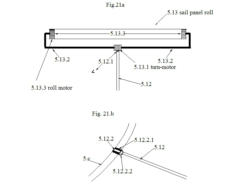
Fig. 21a sail panel roll on bracket, Fig. 21b bracket telescope segment on inner ring construction.
Underneath Fig. 21a describes the design of a sail panel roll 5.13 on itīs bracket. The end of the bracket telescope segment 5.12 holds a turn motor 5.12.1 which can twist the steering sail foils into a propeller like shape and enables turning the sail around itīs pole.
The two roll motors 5.13.3 are the furling motors which work together with winches on the inner ring construction of the sail craft.
Fig.21b pictures the origin of a bracket telescope segment at the inner ring construction.

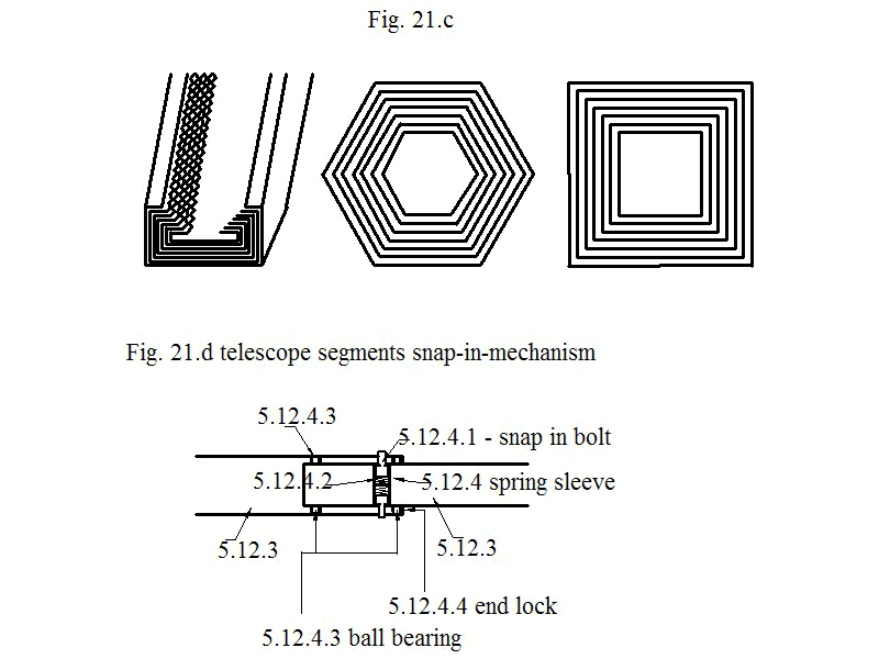
Fig. 21c - some optional telescope bracket types, Fig. 21 d - telescope segment snap in mechanisms

Properties of the in-space enlargeable Solar sail.
Unlike actual designs of self unfolding sails, this in space enlargeable sail unifies some unique properties.
1) It carries a large docking and payload station ( look at Fig. 8b ) able to take in several daughter units, like asteroid landers, telescope or communication units and Mobile Dockingable Thruster Units (MTUīs) which are able to give the mothership an extra acceleration/deceleration-push when needed.
2) The sailcraft is outfitted with large solar cell arrays which enable the craft to power considerable additional solar electric thruster propulsion or to provide sufficient power for daughter units or to recharge them.
3) It is highly steer and maneuverable through the built in SEP-thruster-units. Those thruster may also be used for additional propulsion.
4) It has a fuelless attitude control-system (ACS) which enables along with the large solar cell capacity a long time of serice without refuelling, for instance as satellite system.
5) The sail can reach itīs target orbit in a short time, foregoing Earthīs gravitational well with the strong launcher, pushing it directly onto Sun orbit when needed, getting also additional help through the inbuilt SEP-thrusters and additional mobile dockingable Thruster Units
for deceleration and return tasks. The long and painfull spiraling outwards of piggy back launched solar sails would be avoided.
As the inventor sees it, the only issue is the considerable mass penalty compared to other solar sails. This is caused through the heavy stiff sail roll brackets which will have a lot more mass than todays self employing masts of first generation unfolding square sails.
For satellite purposes however the mass/sail area proportion is not so important, since the sail propulsion is mainly used for fuelless station keeping and attitude control in this case.
Usage and Missions
1.a - Satellite-purposes like Sun observation, keeping the solar sail satellite on near Sun orbits.
1.b - Communication stations to build up high gain communication networks around Sun, the inner planets Mercury, Venus, Earth and Mars, the inner planets moons and Near Earth Asteroids.
2. Asteroid Explorers as mother unit for asteroid landing / prospecting and material return missions.
3. Usage as space tugs with the help of whinch units and itīs solar electric propulsion.
4. Usage as delivery spacecrafts for smaller payloads.
to the next Solar Sail Launch System
Fig.1 -
Fig.2a-2b -
Fig.2c -
Fig.2d -
Fig.3a-3b -
Fig.4a-4c -
Fig.5 -
Fig.6 -
Fig.7 -
Inner Ring -
Flying Ring -
Fig.8 -
Fig.8a -
Fig.8b -
Fig.9 -
Fig.9a -
Fig.10 -
Fig.11 -
Fig.10 -
Fig.11 -
Fig.13 -
Fig.14-15 -
Fig.16 Mobile Thruster Unit -
Fig.17 -
Fig.18 Fuelless Steering -
Fig.19-21d Solar Sail Launch System


